Introduction
The following tutorial demonstrates the capability of ReconOS to create hardware slots which can be reconfigured at runtime. As ReconOS v4 supports the use of Xilinx’s Vivado Design Suite, we will use the partial reconfiguration feature of the latter to create reconfigurable hardware slots and partial bitfiles for each hardware thread (HWT). The demo application used in this tutorial will run the sort demo with up to two hardware threads and then reconfigure the slots to instantiate hardware threads executing the matrix multiplication demo. The tutorial on partial reconfiguration and the Tcl scripts are taken from the Xilinx Application Note 1231 and adapted to Vivado 2017.1 [1][2]. All demo files are available in the ReconOS repository.
Configuration File
Let’s start by looking at the build.cfg file controlling the creation of the ReconOS project. It is very similar to the build.cfg used in the other demos, except for the specification of the threads:
[ReconosThread@Reconf]
Slot = ReconfSortMatrixmul(*)
HwSource = vhdl
ResourceGroup = Resources

[ReconosThread@Sortdemo]
SwSource = c
ResourceGroup = Resources

[ReconosThread@MatrixMul]
SwSource = c
ResourceGroup = Resources
This creates three threads. The first thread Reconf is the only specified hardware thread and acts as a placeholder since the associated hardware slots will later be marked as blackboxes and filled with the functionality of the sortdemo and matrix multiplication during partial reconfiguration. The other two threads are software-only threads. The ReconOS build script will thus create three important C-functions for thread creation: One for the delegate threads of the reconfigurable hardware slot, one for sortdemo software threads and one for matrixmul software threads.
Creating The Bitfiles
The ReconOS project creation scripts do not support reconfigurable hardware slots off-the-shelf, so we have to manually modify the generated Vivado project to create partial bitfiles. First, generate the ReconOS Vivado project by navigating into the demo folder reconf_sort_matrixmul and running the export_hw command:
> rdk export_hw
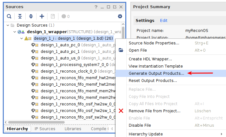
Start the Vivado IDE and open the generated Vivado project, located at build.hw/myReconOS.xpr. Now generate the output products by right-clicking on the design_1_i block diagram. In the following dialog, choose global synthesis as we need to modify the sources before synthesis.
We need to modify the vhdl source file of each hardware slot to mark it as black box. Unfortunately, these files are auto-generated and hence write-protected in Vivado, so they need to be modified outside of Vivado. For slot 0, the file is located at build.hw/myReconOS.srcs/sources_1/bd/design_1/ip/design_1_slot_0_0/synth/design_1_slot_0_0.vhd. Open the files for both slot 0 and 1 in a text editor and add the following attributes:
design_1_slot_0_0.vhd
@@ -120,4 +120,6 @@
		ATTRIBUTE X_INTERFACE_INFO OF HWT_Clk: SIGNAL IS "xilinx.com:signal:clock:1.0 HWT_Clk CLK";
  		ATTRIBUTE X_INTERFACE_INFO OF HWT_Rst: SIGNAL IS "xilinx.com:signal:reset:1.0 HWT_Rst RST";
+		ATTRIBUTE BLACK_BOX : STRING;
+ 		ATTRIBUTE BLACK_BOX OF design_1_slot_0_0_arch : ARCHITECTURE IS "yes";
	BEGIN
		U0 : rt_reconf
design_1_slot_1_0.vhd
@@ -120,4 +120,6 @@
		ATTRIBUTE X_INTERFACE_INFO OF HWT_Clk: SIGNAL IS "xilinx.com:signal:clock:1.0 HWT_Clk CLK";
  		ATTRIBUTE X_INTERFACE_INFO OF HWT_Rst: SIGNAL IS "xilinx.com:signal:reset:1.0 HWT_Rst RST";
+  		ATTRIBUTE BLACK_BOX : STRING;
+ 		ATTRIBUTE BLACK_BOX OF design_1_slot_1_0_arch : ARCHITECTURE IS "yes";
	BEGIN
  		U0 : rt_reconf
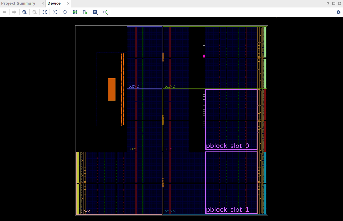
Run synthesis in the Vivado IDE and open the synthesized design. The warnings about black box cells can be ignored, as this is the intended behaviour. In the netlist, expand the nets of design_1_i and look for slot_0 and slot_1. In contrast to other nets, the icon next to their names should be grey and not white. If this is not the case, they have not been sucessfully marked as black boxes. Right-click on each slot and assign a pblock via Floorplanning->Draw Pblock and leave the default name of the pblock unchanged. Make sure that the blocks are large enough and contain enough resources to accomodate the sort and matrix multiplication demo. An exemplary floorplan is shown in the following picture:
Enter the following commands into the Tcl console:
> set_property RESET_AFTER_RECONFIG true [get_pblocks pblock_slot_0]
> set_property HD.RECONFIGURABLE true [get_cells design_1_i/slot_0]
> set_property SNAPPING_MODE ON [get_pblocks pblock_slot_0]
> set_property RESET_AFTER_RECONFIG true [get_pblocks pblock_slot_1]
> set_property HD.RECONFIGURABLE true [get_cells design_1_i/slot_1]
> set_property SNAPPING_MODE ON [get_pblocks pblock_slot_1]
The commands have the following effects:
- RESET_AFTER_RECONFIG makes sure that the module is resetted after reconfiguration
- HD.RECONFIGURABLE marks the black blox as a reconfigurable module
- SNAPPING_MODE aligns the pblock to valid boundaries
Save the changes to the constraints by clicking the save icon in the upper left corner of Vivado. In the following dialog, leave everything unchanged and set the filename of the new constraint file to design_1_pblocks. You can now close the synthesized design and re-run synthesis to bring the synthesized design up-to-date. After synthesis is finished, close the Vivado IDE.
The project-based flow of the Vivado IDE does not support partial reconfiguration for block design modules, hence we have to switch to a non-project Tcl-based approach to generate the bitfiles. Xilinx provides a Tcl script which was modified to fit to the demo files. Before executing the script, the black box attribute of the two hardware slots needs to be removed, because they are now filled with the actual hardware threads. We do this by commenting out both attributes.
design_1_slot_0_0.vhd
@@ -120,6 +120,6 @@
		ATTRIBUTE X_INTERFACE_INFO OF HWT_Clk: SIGNAL IS "xilinx.com:signal:clock:1.0 HWT_Clk CLK";
  		ATTRIBUTE X_INTERFACE_INFO OF HWT_Rst: SIGNAL IS "xilinx.com:signal:reset:1.0 HWT_Rst RST";
-		ATTRIBUTE BLACK_BOX : STRING;
- 		ATTRIBUTE BLACK_BOX OF design_1_slot_0_0_arch : ARCHITECTURE IS "yes";
+		--ATTRIBUTE BLACK_BOX : STRING;
+ 		--ATTRIBUTE BLACK_BOX OF design_1_slot_0_0_arch : ARCHITECTURE IS "yes";
	BEGIN
		U0 : rt_reconf
design_1_slot_1_0.vhd
@@ -120,6 +120,6 @@
		ATTRIBUTE X_INTERFACE_INFO OF HWT_Clk: SIGNAL IS "xilinx.com:signal:clock:1.0 HWT_Clk CLK";
  		ATTRIBUTE X_INTERFACE_INFO OF HWT_Rst: SIGNAL IS "xilinx.com:signal:reset:1.0 HWT_Rst RST";
-  		ATTRIBUTE BLACK_BOX : STRING;
- 		ATTRIBUTE BLACK_BOX OF design_1_slot_1_0_arch : ARCHITECTURE IS "yes";
+  		--ATTRIBUTE BLACK_BOX : STRING;
+ 		--ATTRIBUTE BLACK_BOX OF design_1_slot_1_0_arch : ARCHITECTURE IS "yes";
	BEGIN
  		U0 : rt_reconf
The Tcl script, located at /scripts/design.tcl, automatically generates two full bitfiles (one sortdemo configuration and one matrix multiplication configuration) and four partial bitfiles (sortdemo and matrix multiplication for each of the two hardware slots). The script uses synthesis checkpoints and constraints of the static design, which was previously synthesized. Keep this in mind before overwriting the Vivado project folder build.hw. For more detailed information on the script, see the comments in the Tcl sources or consult [2]. Execute the script with the following command:
> vivado -mode batch -source ./scripts/design.tcl -notrace
The generated bitfiles are in the folder Bitstreams:
config_matrixmul.bit: A configuration with two matrixmul hardware threadsconfig_sortdemo.bit: A configuration with two sortdemo hardware threadsconfig_matrixmul_pblock_slot_0_partial.bit: Partial bitfile to reconfigure hardware slot 0 with a matrixmul hardware thread- Other partial bitfiles with the same naming scheme
As the demo starts with the sortdemo and then uses partial reconfiguration to switch to matrix multiplication HWTs, the demo only needs the full sortdemo configuration and the partial bitfiles of the matrix multiplication.
Using Dynamic Reconfiguration in Software
The main steps of using dynamically reconfigurable hardware slots for this demo include:
- Create a delegate thread for each reconfigurable hardware slot using the function
reconos_create_hwt_reconf(). The FPGA is initizalized with the sortdemo configuration, so this will create sortdemo hardware threads. - Run the portion of the code belonging to the sortdemo
- Stop the hardware threads by calling
reconos_thread_suspend_block()on the hardware slot which should be reconfigured. In order for this to work properly, the currently running HWT must exit only whenHWT_signalis set. For more details, see the demo’s vhdl sources of the threads. Additonally, all threads must rely onmbox_tryget()calls instead of uninterruptiblembox_get()calls. - Reconfigure the hardware slot by writing the slot’s partial bitfile of the matrix multiplication to
/dev/xdevcfg - Resume the delegate thread by calling
reconos_thread_resume()on the reconfigured hardware slot - Run the portion of the code belonging to the matrix multiplication
For a detailed understanding of the flow, it is inevitable to study the main.c file of this demo.
Running the Demo
In the demo project folder, compile the software by using the ReconOS development kit (see the commands below). The executable can then be found at build.sw/reconfsortmatrix.
> rdk export_sw
> rdk build_sw
Create a folder for the demo in the nfs share and copy the executable reconfsortmatrix, the bitfile config_sortdemo.bit and the two partial bitfiles config_matrixmul_pblock_slot_0_partial.bit and config_matrixmul_pblock_slot_1_partial.bit into the folder. Connect to the UART of the Zedboard, e.g. with picocom, boot linux and navigate to the just created folder. Before we can run a ReconOS program, we need to load the ReconOS kernel module. Loading the kernel module requires a configured FPGA. Hence, program the FPGA with the config_sortdemo.bit bitfile and then execute the reconos_init script. Upon initialization, the kernel module determines the number of hardware slots of the currently loaded bitfile, so it is highly recommended not to load an arbitrary bitfile into the FPGA, but instead one of the bitfiles from this demo.
> sudo picocom -b 115200 /dev/ttyACM0
Zynq> boot
/ # cd PATH_TO_DEMO_FOLDER
/demo_folder # cat config_sortdemo.bit > /dev/xdevcfg     # Program the FPGA
/demo_folder # ./reconos_init.sh                          # Initizalize kernel module. Make sure that mreconos.ko is in same folder as init script
With everything set up, we can now run the demo. The first argument is the number of used hardware threads (limited to 2 for this demo), the second argument is the number of software threads, the third argument is the number of blocks to sort and the fourth argument is the size of the multiplicated matrices. For instance, sorting 32 blocks and then multiplying matrices with a size of 256 using 2 hardware threads would require the following command:
/demo_folder # ./reconfsortmatrixmul 2 0 32 256
If the run was successful, the demo outputs several timing measurements before termination. This concludes our demo on dynamic reconfiguration of hardware threads. Have fun adapting these concepts to your own applications!